Next: Conventional active inductor Up: Active inductor Previous: Active inductor
One of the most popular ways to realize an active inductor is
using a gyrator. Figure 1(a) shows an active inductor
based on a gyrator. A gyrator consists of two transconductors (OTAs)
whose input terminals are connected to an output terminal of another
transconductor. When a capacitor ![]() is connected to one of input
terminals, input admittance at another input terminal becomes
is connected to one of input
terminals, input admittance at another input terminal becomes
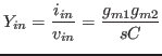
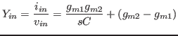
Figure 2(a) shows another active inductor. A capacitor
![]() is inserted between two input terminals of transconductors. Input
admittance of the active inductor is
is inserted between two input terminals of transconductors. Input
admittance of the active inductor is
Transconductors used for an active inductors are usually realized by
MOSFETs. Actual transconductors have non-ideal characteristics, for
example, they have an input capacitance and an output resistance. Taking
these parasitic elements into consideration a more accurate equivalent
circuit of an active inductor shown in Fig. 3 is
obtained. A active inductor contains a series resistance ![]() , a
parallel resistance
, a
parallel resistance ![]() and input capacitance
and input capacitance ![]() except inductor
except inductor
![]() . A lot of active inductors can be represented by this equivalent
circuit. Values of elements depend on the circuit
configuration. Elements values shown in Fig.3 are those
of Fig. 1(a) where
. A lot of active inductors can be represented by this equivalent
circuit. Values of elements depend on the circuit
configuration. Elements values shown in Fig.3 are those
of Fig. 1(a) where ![]() and
and ![]() are an
input capacitance and an output resistance of transconductors.
are an
input capacitance and an output resistance of transconductors.
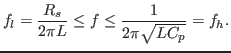
Input impedance of Fig. 3 depends on a frequency. The
frequency range where an active inductor simulates an inductor is
Takahide Sato 2012-03-31
![\includegraphics[scale=0.5]{gyrator_new1_1.eps}](img6.png)
![\includegraphics[scale=0.5]{gyrator_new2_1.eps}](img11.png)
![\includegraphics[scale=0.65]{ind3_1.eps}](img19.png)